

Here we would like to explain the quality management procedure of neodymium magnets, which are well-known typical rare earth magnets. On our website, we have introduced the production sites, with the cooperation of our OEM manufacturer in China. (The procedures for quality management also differ slightly due to the different production procedures depending on the material such as ferrite magnet, samarium cobalt magnet etc.) In order to prevent defected products from being shipped out, design, production and finishing procedures are managed and inspected strictly by our company’s employees that have been assigned in China. We are committed to improvements and identifying the source of any issues by traceability, in the event of any failures.


The below standard for sampling inspection is one of the standards set by Japanese Industrial Standards Committee. The inspection standard and number of samples (N) can be determined as necessary. The variability, tolerance and standard deviation is dependent on, and determined by the number of samples. Inspection standard: JIS Z9015/Inspection standard S4/AQL 1%
| Lot size | Strict inspection | Average inspection | Lenient inspection | |||||
| (Number in 1 lot) | Number of samples | Number required for pass | Number of samples | Number required for pass | Number of samples | Number required for pass | ||
| 2 | 〜 | 8 | 2 | Below 0 | 2 | Below 0 | 2 | Below 0 |
| 9 | 〜 | 15 | 2 | Below 0 | 2 | Below 0 | 2 | Below 0 |
| 16 | 〜 | 2 | 3 | Below 0 | 3 | Below 0 | 2 | Below 0 |
| 26 | 〜 | 50 | 5 | Below 0 | 5 | Below 0 | 2 | Below 0 |
| 51 | 〜 | 90 | 5 | Below 0 | 5 | Below 0 | 2 | Below 0 |
| 91 | 〜 | 150 | 8 | Below 0 | 8 | Below 0 | 3 | Below 0 |
| 151 | 〜 | 280 | 13 | Below 0 | 13 | Below 0 | 5 | Below 0 |
| 281 | 〜 | 500 | 13 | Below 0 | 13 | Below 0 | 5 | Below 0 |
| 501 | 〜 | 1,200 | 20 | Below 0 | 20 | Below 0 | 8 | Below 0 |
| 1,201 | 〜 | 3,200 | 32 | Below 1 | 32 | Below 1 | 13 | Below 1 |
| 3,201 | 〜 | 10,000 | 32 | Below 1 | 32 | Below 1 | 13 | Below 1 |
| 10,001 | 〜 | 35,000 | 50 | Below 1 | 50 | Below 1 | 20 | Below 1 |
| 35,001 | 〜 | 150,000 | 80 | Below 1 | 80 | Below 2 | 32 | Below 1 |
| 150,001 | 〜 | 500,000 | 80 | Below 1 | 80 | Below 2 | 32 | Below 1 |
| 500,001 | 〜 | 125 | Below 2 | 125 | Below 3 | 50 | Below 2 | |
Appearance inspections are all conducted visually. Since the inspections are visual inspections, unfortunately it is not possible to prevent all defects in appearance and other failures. The permissible range for appearance defects varies according to the size. In principle, the permissible ranges are determined as below. Permissible ranges are determined beforehand and set forth in the product specification for products for which appearance is considered important and require mechanical strength. It is not possible to completely prevent chips and scratches on magnets as they have similar physical characteristics to china and glass and thus break easily. Therefore, unless there is a large chip that may weaken the magnetic characteristics or surface treatment that is stripping off which may lead to corrosion, the product will be accepted under concession.
Boundary sample for appearance
| Item | Diagram | Dimension | A | B | C | Accepted number of defects | Remarks | Pass | Fail | ||
| Chipped pole face | 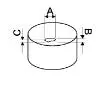 |
φ5 | ≦1.0mm | ≦1.0mm | ≦0.5mm | ≦1pc | There must be surface treatment on the chipped area |  |
 |
 |
|
| φ10 | ≦2.0mm | ≦2.0mm | ≦1.0mm | ≦1pc | |||||||
| φ20 | ≦2.0mm | ≦2.0mm | ≦1.0mm | ≦1pc | |||||||
| φ30 | ≦2.5mm | ≦2.5mm | ≦2.0mm | ≦1pc | |||||||
| φ40 | ≦2.5mm | ≦2.5mm | ≦2.0mm | ≦1pc | |||||||
| φ50 | ≦3.0mm | ≦3.0mm | ≦2.5mm | ≦1pc | |||||||
| Chipped pole face | 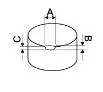 |
φ5 | ≦1.0mm | ≦1.0mm | ≦0.5mm | ≦2pc | There must be surface treatment on the chipped area |
 |
 |
 |
 |
| φ10 | ≦2.0mm | ≦2.0mm | ≦1.0mm | ≦2pc | |||||||
| φ20 | ≦2.0mm | ≦2.0mm | ≦1.0mm | ≦2pc | |||||||
| φ30 | ≦2.5mm | ≦2.5mm | ≦2.0mm | ≦2pc | |||||||
| φ40 | ≦2.5mm | ≦2.5mm | ≦2.0mm | ≦2pc | |||||||
| φ50 | ≦3.0mm | ≦3.0mm | ≦2.5mm | ≦2pc | |||||||
| Pinhole |  |
All | ≦0.5mm | - | - | ≦2pc | There must be surface treatment on the pinhole area |
||||
| Scratches |  |
Scratches, ex. by nails are not acceptable | There must be surface treatment on the scratched area |
 |
|||||||
| Crack |  |
All not acceptable | Determine whether it is a crack or streak |  |
|||||||
| Discoloration due to rust |  |
There must be no discoloration due to rust and no areas may be have any bulging or paint stripping off |  |
 |
 |
||||||
※1 All items will be determined by visual inspection.※2 In cases which the inspection standards are set according to the boundary samples, the boundary samples shall take precedence.
There are various types of magnetic measuring devices that measure magnetic forces, depending on the inspection purposes. Below are typical measuring devices that are used mainly in the magnet industry.
| Manufacturer | Type | Hall effect element probe |
Image of probe | Neodymium magnet φ10mm×10mm |
Remarks |
| Denshijiki Industry Co. | GM-4002 | T-401 |  |
506.5mT | Floor standing type |
| T-402 | 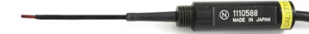 |
535.1mT | Floor standing type | ||
| KANETEC Co. | TM-601 | TM-601PRB |  |
488.0mT | Mobile type Simple accuracy device |
| Magfine Corporation | Magnetic calculator | 494.1mT | Predicted values based on magnetic calculations |
Difference in measurement results due to difference in measurement device and probe. Testing material neodymium magnet φ10mm×10mm
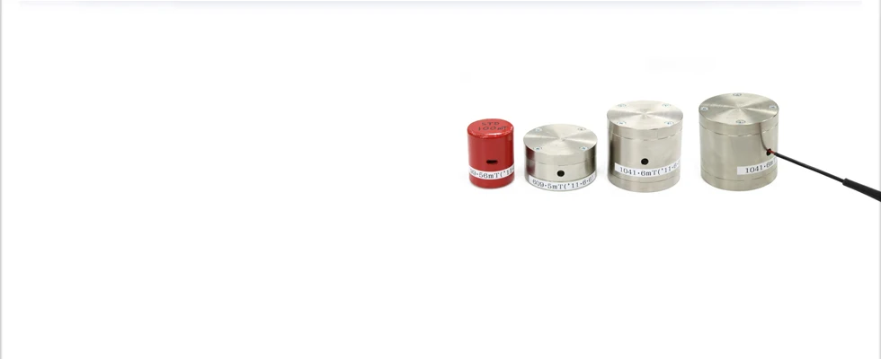
A magnet that corrects or calibrates errors of tesla/gauss meters and fluxmeters are called standard magnets. Since tesla/gauss meters are precision devices, errors may occur due to age and environment. Even if such errors occur, these testing devices are designed so that they cannot be manually corrected. Therefore, standard magnets are used to conduct regular tests of the meters in order to calibrate any errors. The standard magnets are also regularly tested at a testing institution to check they meet magnet industry standards.
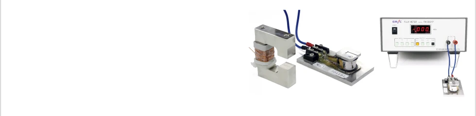
A fluxmeter measures the total flux and can accurately and quickly inspect a large volume of magnets to check which ones have a large or small variation in the characteristics. It is suitable when all the products need to be inspected or a large volume inspection is required. The unit used is Wb or Mx. It is necessary to build a search coil that suits the magnet to be tested so that it is possible to measure the variation of the total flux when the magnet is removed from the search coil.
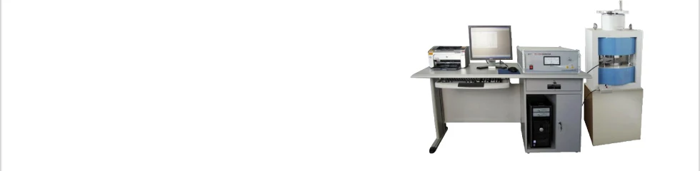
The BH analyzer measures the magnetic characteristics of magnetic material which then makes it possible to find out the demagnetization characteristics and energy product that is necessary for designing magnetic circuits. It can also check whether the values of the magnetic characteristics which are set forth for each magnetic material are within the specification range. In order to measure the characteristics, a powerful electromagnetic field and a power-supply device with a high voltage is required. It is mostly used at magnet manufacturing plants and magnet research and development institutions.
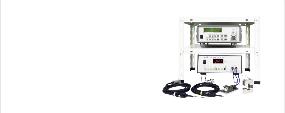
The tesla meter or gauss meter measures magnetic flux density. A hall effect device is set up on the magnet surface or other surface and the density of the magnetic flux that passes through an area of 1cm2 . According to the definition of magnetic flux density, when 1 Mx of magnetic flux perpendicularly intercrosses, the magnetic flux density is 1 gauss. The unit commonly used for measuring devices is tesla or gauss. It is most widely used out of all the magnetic testing devices since it can easily check magnetic characteristics. The measurement values may largely vary because they are easily affected by the testing environment and testing method. Therefore even if the same magnet is tested by the same person in the same environment, in some cases, the measurement values may differ largely depending on the manufacturer, type, accuracy of the probe(hall effect device) , points measured on the surface and room temperature. Since the measurement enviroment criteria depend on the usage environment, absolute values like dimension tolerances cannot be indicated. For that reason, there may be a large difference in the measurements values indicated on our products and customer's measurement values. Measurement methods and environments differ according to the manufacturer and the testing standards within the industry are also not the same. The testing environment and magnetic flux density that shall serve as the standard shall be determined based on the testing environment used by the user.